Zero Knowledge Proof — A Guide to Halo2 Source Code
In order to understand Halo2, it’s a great start from two parts: 1/ circuit construction 2/ proof system. From developers’ perspective, circuit construction is the basic interface. The key to understand circuit construction is to figure out how to build circuits, and how these circuits are represented within Halo2. This article will discuss the Halo2 circuit constrcution and deep dive into source code in an easy-to-understand approach.
Preface
Before deep diving into Halo2 circuit or proof system, please go through the documentation to get a basic understanding:
https://zcash.github.io/halo2/index.html
The corresponding translation in Chinese:
https://trapdoor-tech.github.io/halo2-book-chinese/
Source Code Structure
Halo2 source code download address:
https://github.com/zcash/halo2.git
Please find the last commit referenced in this article below:
commit 658c2db4217b1b19b17ecd29577c0e370e1c4997
Merge: 3850b9c b46ef35
Author: str4d <jack@electriccoin.co>
Date: Sat Oct 2 01:54:55 2021 +1300
Merge pull request #374 from zcash/trait-usage
Clean up our trait usageSource code stucture of Halo2 as follows:

Please check the main logic implemented in src, check the Benchmark test codes in benches, and find the description documentation for Halo2 in book. Also some circuit samples are provided in examples directory.
Circuit Structure
Before going into details, let’s get a whole view of circuit structure of Halo2. There are some differences between the circuit structures of Halo2 and PLONK/Groth16. In simple words, PLONK/Groth16 constraint system is composed by independent constraints which means each one of the constraints only effects on the variables on its own row, and only supports certain computation, which is multiplication or a combination with addition). Constraints in Halo2 are not limited to reference the variables in its own row — the “custom gate” is useful to assign a specific constraint to compute as requested.
Below is the overall circuit structure:
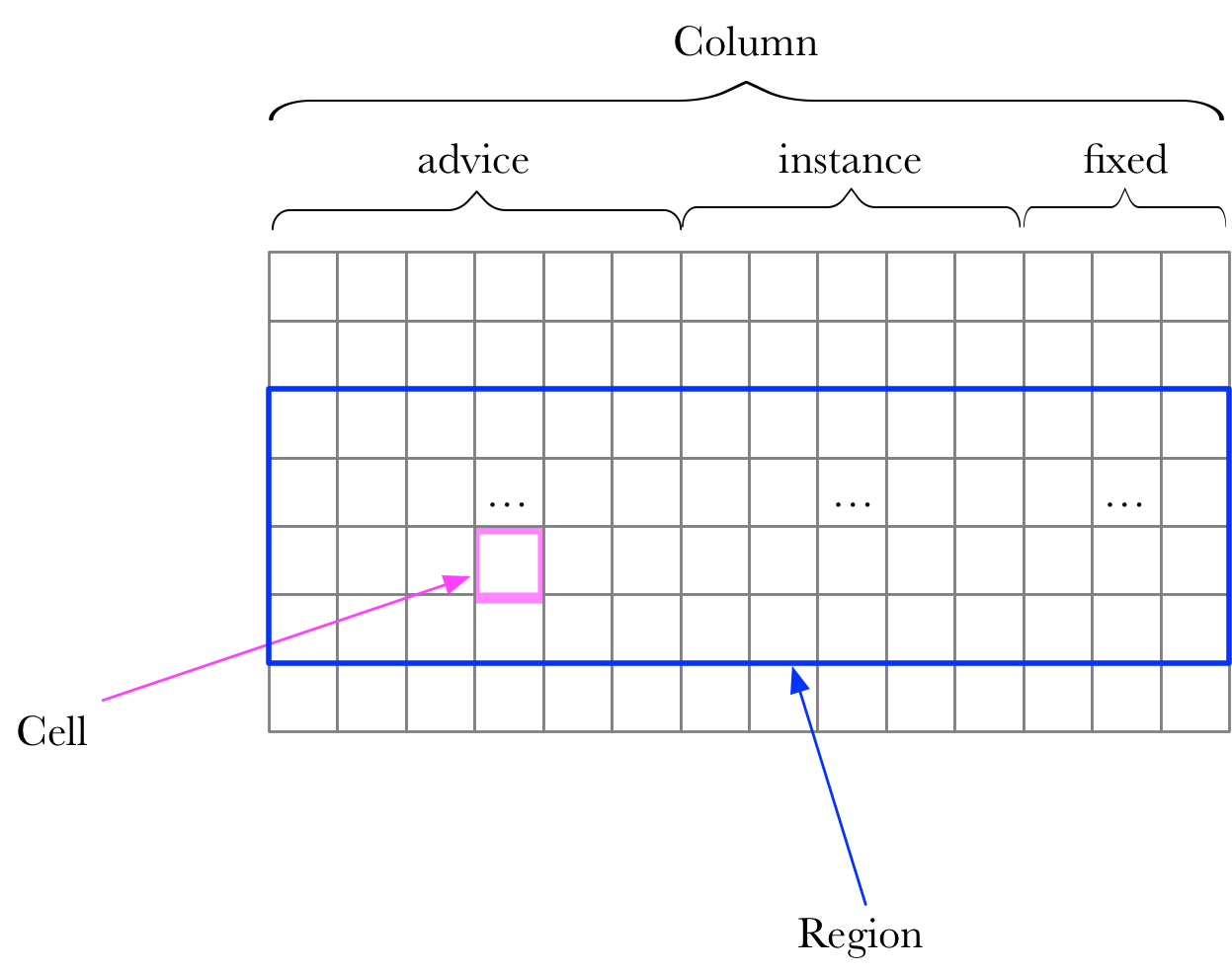
Circuits are composed by Columns and Rows. Columns have three different types: advice, instance and selector, which are defined in src/plonk/circuit.rs.
pub enum Any {
  Advice,
  Fixed,
  Instance,
}
Column Advice is the witness, and Column Instance is public message. Column Selector are used to turn gates on and off, and are allocated using ConstraintSystem::query_selector. And Selectors are a higher-layer abstraction built on top of fixed columns. To modularize a circuit, generally it’s better to construct circuits based on a Region. A circuit module can be “copied” into different Region.
Cell is defined in src/circuit.rs:
pub struct Cell {
  region_index: RegionIndex,
  row_offset: usize,
  column: Column<Any>,
}
Cell means a certain Column and a certain Row in a Region.
Terminologies
To understand Halo2 circuit construction, let’s start with a simple example: examples/simple-example.rs. It’s necessary to clerify the terminologies below before that.
Chip
Essentially, Circuit is constructed by multiple Chips organized in a certain logic. To creat a Chip starts with “Config”.
Config
Config includes the required Columns and logical meaning of Column Fixed. These Configs could be Custom Gate, or lookup.
Instructions
Each Chip comes with Instructions. Partial or all functions of a Chip will be added to the circuit with calling the Instructions.
Layouter
Layout is required to add Chip to a circuit. Layouter is called to implement a layout. Layouter interface is defined in src/circuit.rs:
pub trait Layouter<F: Field> {
type Root: Layouter<F>;
fn assign_region<A, AR, N, NR>(&mut self, name: N, assignment: A) -> Result<AR, Error>
where
A: FnMut(Region<'_, F>) -> Result<AR, Error>,
N: Fn() -> NR,
NR: Into<String>;
fn assign_table<A, N, NR>(&mut self, name: N, assignment: A) -> Result<(), Error>
where
A: FnMut(Table<'_, F>) -> Result<(), Error>,
N: Fn() -> NR,
NR: Into<String>;
fn constrain_instance(
&mut self,
cell: Cell,
column: Column<Instance>,
row: usize,
) -> Result<(), Error>;
fn get_root(&mut self) -> &mut Self::Root;
fn push_namespace<NR, N>(&mut self, name_fn: N)
where
NR: Into<String>,
N: FnOnce() -> NR;
fn pop_namespace(&mut self, gadget_name: Option<String>);
fn namespace<NR, N>(&mut self, name_fn: N) -> NamespacedLayouter<'_, F, Self::Root>
where
NR: Into<String>,
N: FnOnce() -> NR,
{
self.get_root().push_namespace(name_fn);
NamespacedLayouter(self.get_root(), PhantomData)
}
}There exsits Hierarchy relationship in Layouter. Therefore, Layouter interface defines get_root/push_namespace/pop_namespace/namespace functions. The core logic is in the following 3 functions:
- assign_region — get a region, in which various assignments can be executed. This is defined in RegionLayouter interface.
- assign_table — get a table and configure the table. This is defined in TableLayouter interface.
- constrain_instance — restrict a Cell to be consistent with a Cell in Column Instance.
Assignment
Assignment is the interface for assigning values in a circuit, which is defined in src/plonk/circuit.rs:
pub trait Assignment<F: Field> {
fn enter_region<NR, N>(&mut self, name_fn: N)
where
NR: Into<String>,
N: FnOnce() -> NR;
fn exit_region(&mut self);
fn enable_selector<A, AR>(
&mut self,
annotation: A,
selector: &Selector,
row: usize,
) -> Result<(), Error>
where
A: FnOnce() -> AR,
AR: Into<String>;
fn query_instance(&self, column: Column<Instance>, row: usize) -> Result<Option<F>, Error>;
fn assign_advice<V, VR, A, AR>(
&mut self,
annotation: A,
column: Column<Advice>,
row: usize,
to: V,
) -> Result<(), Error>
where
V: FnOnce() -> Result<VR, Error>,
VR: Into<Assigned<F>>,
A: FnOnce() -> AR,
AR: Into<String>;
fn assign_fixed<V, VR, A, AR>(
&mut self,
annotation: A,
column: Column<Fixed>,
row: usize,
to: V,
) -> Result<(), Error>
where
V: FnOnce() -> Result<VR, Error>,
VR: Into<Assigned<F>>,
A: FnOnce() -> AR,
AR: Into<String>;
fn copy(
&mut self,
left_column: Column<Any>,
left_row: usize,
right_column: Column<Any>,
right_row: usize,
) -> Result<(), Error>;
fn fill_from_row(
&mut self,
column: Column<Fixed>,
row: usize,
to: Option<Assigned<F>>,
) -> Result<(), Error>;
fn push_namespace<NR, N>(&mut self, name_fn: N)
where
NR: Into<String>,
N: FnOnce() -> NR;
fn pop_namespace(&mut self, gadget_name: Option<String>);
}Circuit Internal Framework
To simplify the development of circuits, the Layouter is an important abastracted component to form circuit internal framework in Halo2 (see an example of SimpleFloorPlanner):
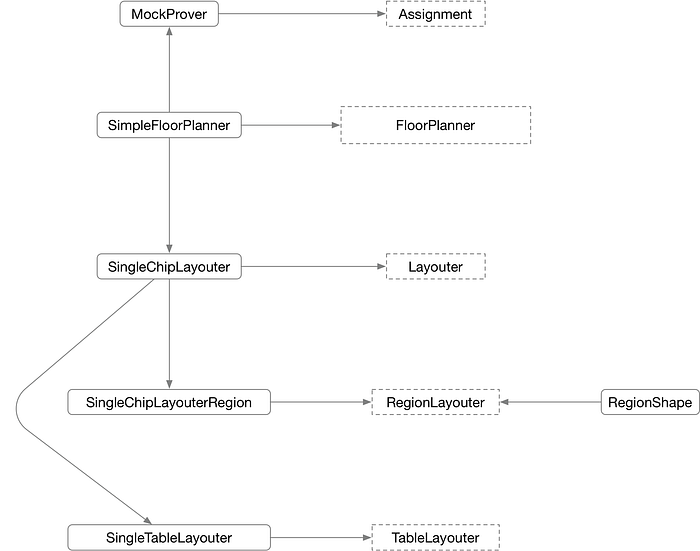
Two methods to implement the Layouter could be found in the example: 1/ SimpleFloorPlanner 2/ V1/V1Plan. Let’s have a close look at SimpleFloorPlanner to understand the logic of Halo2. The framework consists of four interfaces: FloorPlanner, Layouter, RegionLayout/TableLayout and Assignment.
In short, a FloorPlanner has one Layouter, and each Layouter can have multiple RegionLayouts or TableLayouts. Circuits makes Cell assignment through the Assignment interface.
Let’s check out the calling relationships among these interfaces:
- SimpleFloorPlanner is the implementation for FloorPlanner, which is defined in src/circuit/floor_planner/single_pass.rs:
pub struct SimpleFloorPlanner;impl FloorPlanner for SimpleFloorPlanner {
    fn synthesize<F: Field, CS: Assignment<F>, C: Circuit<F>>(
        cs: &mut CS,
        circuit: &C,
        config: C::Config,
        constants: Vec<Column<Fixed>>,
    ) -> Result<(), Error> {
        let layouter = SingleChipLayouter::new(cs, constants)?;
        circuit.synthesize(config, layouter)
    }
}
SimpleFloorPlanner implements the synthesize function for FloorPlanner interface. It is easy to see this function creates the SingleChipLayouter object, and directly calls the synthesize function to start synthesize a circuit.
- SingleChipLayouter is defined in src/circuit/floor_planner/single_pass.rs, including all the information of a circuit:
pub struct SingleChipLayouter<'a, F: Field, CS: Assignment<F> + 'a> {
    cs: &'a mut CS,
    constants: Vec<Column<Fixed>>,
    /// Stores the starting row for each region.
    regions: Vec<RegionStart>,
    /// Stores the first empty row for each column.
    columns: HashMap<RegionColumn, usize>,
    /// Stores the table fixed columns.
    table_columns: Vec<TableColumn>,
    _marker: PhantomData<F>,
}
It’s simple to manage the Region in SingleChipLayouter, one entire row is belong to a Region and the regions record the offset of the rows in each Region. The cs implements the Assignment interface, storing the assignment information of all circuits. The columns records the offset of corresponding empty row of current RegionColumn. The table_columns records information of Column Fixed required by the Table. To sum up, SingleChipLayouter has all information of a circuit, including layouts.
- SingleChipLayouter’s assign_region function implements the synthesize process of a Region. In simple words, the main logic of this function is to create a region, and transform the region layout into global layout, which can be separated into two parts:
- 1/ Get the Region “shape” through RegionShape. The “shape” incudes the needed Column information.
- 2/ Based on the Column information acquired from previous step, find the start question without conflictions with any other Regions.
- It’s helpful to read the comments in codes to understand the logic:
fn assign_region<A, AR, N, NR>(&mut self, name: N, mut assignment: A) -> Result<AR, Error>
where
    A: FnMut(Region<'_, F>) -> Result<AR, Error>,
    N: Fn() -> NR,
    NR: Into<String>,
{
    let region_index = self.regions.len(); //Get the index of the region// Get shape of the region. //use RegionShape's Region interface,collect the circuit info
    let mut shape = RegionShape::new(region_index.into());
    {
        let region: &mut dyn RegionLayouter<F> = &mut shape;
        assignment(region.into())?;
    }// Lay out this region. We implement the simplest approach here: position the
    // region starting at the earliest row for which none of the columns are in use.
    let mut region_start = 0; //According the used column information, choose the correct region start.
    for column in &shape.columns {
        region_start = cmp::max(region_start, self.columns.get(column).cloned().unwrap_or(0));
    }
    self.regions.push(region_start.into());// Update column usage information. //Record down all column information
    for column in shape.columns {
        self.columns.insert(column, region_start + shape.row_count);
    }// Assign region cells.
    self.cs.enter_region(name); //Enter the region
    let mut region = SingleChipLayouterRegion::new(self, region_index.into());
    let result = {
        let region: &mut dyn RegionLayouter<F> = &mut region;
        assignment(region.into()) //Use SingleChipLayouterRegion to assign variables
    }?;
    let constants_to_assign = region.constants;
    self.cs.exit_region(); //Exit the region// Assign constants. For the simple floor planner, we assign constants in order in
    // the first `constants` column.
    if self.constants.is_empty() {
        if !constants_to_assign.is_empty() {
            return Err(Error::NotEnoughColumnsForConstants);
        }
    } else {
        let constants_column = self.constants[0];
        let next_constant_row = self
            .columns
            .entry(Column::<Any>::from(constants_column).into())
            .or_default();
        for (constant, advice) in constants_to_assign {
            self.cs.assign_fixed(
                || format!("Constant({:?})", constant.evaluate()),
                constants_column,
                *next_constant_row,
                || Ok(constant),
            )?;
            self.cs.copy(
                constants_column.into(),
                *next_constant_row,
                advice.column,
                *self.regions[*advice.region_index] + advice.row_offset,
            )?;
            *next_constant_row += 1;
        }
    }Ok(result)
}
- Use SingleChipLayouter’s assign_table function to add lookup table logic to current circuit:
fn assign_table<A, N, NR>(&mut self, name: N, mut assignment: A) -> Result<(), Error>
where
    A: FnMut(Table<'_, F>) -> Result<(), Error>,
    N: Fn() -> NR,
    NR: Into<String>,
{
    // Maintenance hazard: there is near-duplicate code in `v1::AssignmentPass::assign_table`.
    // Assign table cells.
    self.cs.enter_region(name); //Enter a region
    let mut table = SimpleTableLayouter::new(self.cs, &self.table_columns);
    {
        let table: &mut dyn TableLayouter<F> = &mut table;
        assignment(table.into()) //Assign the table
    }?;
    let default_and_assigned = table.default_and_assigned;
    self.cs.exit_region(); //Exit the region// Check that all table columns have the same length `first_unused`,
    // and all cells up to that length are assigned.
    let first_unused = {
        match default_and_assigned
            .values()
            .map(|(_, assigned)| {
                if assigned.iter().all(|b| *b) {
                    Some(assigned.len())
                } else {
                    None
                }
            })
            .reduce(|acc, item| match (acc, item) {
                (Some(a), Some(b)) if a == b => Some(a),
                _ => None,
            }) {
            Some(Some(len)) => len,
            _ => return Err(Error::SynthesisError), // TODO better error
        }
    };// Record these columns so that we can prevent them from being used again.
    for column in default_and_assigned.keys() {
        self.table_columns.push(*column);
    }

    for (col, (default_val, _)) in default_and_assigned {
        // default_val must be Some because we must have assigned
        // at least one cell in each column, and in that case we checked
        // that all cells up to first_unused were assigned.
        self.cs
            .fill_from_row(col.inner(), first_unused, default_val.unwrap())?;
    }Ok(())
}
default_and_assigned records the default value in a Column Fixed and configuration of a certain cell.
- SingleChipLayouterRegion implements the Region interface. The assign_advice function is used to assign value to a Cell in Column Advice of the Region:
fn assign_advice<'v>(
    &'v mut self,
    annotation: &'v (dyn Fn() -> String + 'v),
    column: Column<Advice>,
    offset: usize,
    to: &'v mut (dyn FnMut() -> Result<Assigned<F>, Error> + 'v),
) -> Result<Cell, Error> {
    self.layouter.cs.assign_advice(
        annotation,
        column,
        *self.layouter.regions[*self.region_index] + offset,
        to,
    )?;Ok(Cell {
        region_index: self.region_index,
        row_offset: offset,
        column: column.into(),
    })
}
- Use cs.assign_fixed function to assign value to Column Fixed. Please find the implementation of MockProver as reference defined in src/dev.rs.
fn assign_fixed<V, VR, A, AR>(
    &mut self,
    _: A,
    column: Column<Fixed>,
    row: usize,
    to: V,
) -> Result<(), Error>
where
    V: FnOnce() -> Result<VR, Error>,
    VR: Into<Assigned<F>>,
    A: FnOnce() -> AR,
    AR: Into<String>,
{
    ...
    *self
        .fixed
        .get_mut(column.index())
        .and_then(|v| v.get_mut(row))
        .ok_or(Error::BoundsFailure)? = CellValue::Assigned(to()?.into().evaluate());Ok(())
}
- Use cs.copy function to add Permutation information.
fn copy(
    &mut self,
    left_column: Column<Any>,
    left_row: usize,
    right_column: Column<Any>,
    right_row: usize,
) -> Result<(), crate::plonk::Error> {
    if !self.usable_rows.contains(&left_row) || !self.usable_rows.contains(&right_row) {
        return Err(Error::BoundsFailure);
    }self.permutation
        .copy(left_column, left_row, right_column, right_row)
}
Next let us check the RegionLayouter and TableLayouter. RegionLayouter is defined in src/circuit/layouter.rs:
pub trait RegionLayouter<F: Field>: fmt::Debug {
fn enable_selector<'v>(
&'v mut self,
annotation: &'v (dyn Fn() -> String + 'v),
selector: &Selector,
offset: usize,
) -> Result<(), Error>;
fn assign_advice<'v>(
&'v mut self,
annotation: &'v (dyn Fn() -> String + 'v),
column: Column<Advice>,
offset: usize,
to: &'v mut (dyn FnMut() -> Result<Assigned<F>, Error> + 'v),
) -> Result<Cell, Error>;
fn assign_advice_from_constant<'v>(
&'v mut self,
annotation: &'v (dyn Fn() -> String + 'v),
column: Column<Advice>,
offset: usize,
constant: Assigned<F>,
) -> Result<Cell, Error>;
fn assign_advice_from_instance<'v>(
&mut self,
annotation: &'v (dyn Fn() -> String + 'v),
instance: Column<Instance>,
row: usize,
advice: Column<Advice>,
offset: usize,
) -> Result<(Cell, Option<F>), Error>;
fn assign_fixed<'v>(
&'v mut self,
annotation: &'v (dyn Fn() -> String + 'v),
column: Column<Fixed>,
offset: usize,
to: &'v mut (dyn FnMut() -> Result<Assigned<F>, Error> + 'v),
) -> Result<Cell, Error>;
fn constrain_constant(&mut self, cell: Cell, constant: Assigned<F>) -> Result<(), Error>;
fn constrain_equal(&mut self, left: Cell, right: Cell) -> Result<(), Error>;
}The interface RegionLayouter has functions to enable selector, assign values to Cell, and check the equal constraints of left and right Cells, etc.
TableLayouter interface is defined as follows:
pub trait TableLayouter<F: Field>: fmt::Debug {
  fn assign_cell<'v>(
      &'v mut self,
      annotation: &'v (dyn Fn() -> String + 'v),
      column: TableColumn,
      offset: usize,
      to: &'v mut (dyn FnMut() -> Result<Assigned<F>, Error> + 'v),
  ) -> Result<(), Error>;
}
TableLayouter has only one interface: assign_cell to assign value to a Cell in a TableColumn of the table.
Now, the circuit framework is clear: in Halo2, Chip is composed of Regions, and these Regions are organized by Layouters. All information of the circuit is stored in Assignment interface. MockProver is a good reference of the Assignment implementation.
ConstraintSystem
ConstraintSystem describes the information of circuits:
#[derive(Debug, Clone)]
pub struct ConstraintSystem<F: Field> {
pub(crate) num_fixed_columns: usize,
pub(crate) num_advice_columns: usize,
pub(crate) num_instance_columns: usize,
pub(crate) num_selectors: usize,
pub(crate) selector_map: Vec<Column<Fixed>>,
pub(crate) gates: Vec<Gate<F>>,
pub(crate) advice_queries: Vec<(Column<Advice>, Rotation)>,
// Contains an integer for each advice column
// identifying how many distinct queries it has
// so far; should be same length as num_advice_columns.
num_advice_queries: Vec<usize>,
pub(crate) instance_queries: Vec<(Column<Instance>, Rotation)>,
pub(crate) fixed_queries: Vec<(Column<Fixed>, Rotation)>,
// Permutation argument for performing equality constraints
pub(crate) permutation: permutation::Argument,
// Vector of lookup arguments, where each corresponds to a sequence of
// input expressions and a sequence of table expressions involved in the lookup.
pub(crate) lookups: Vec<lookup::Argument<F>>,
// Vector of fixed columns, which can be used to store constant values
// that are copied into advice columns.
pub(crate) constants: Vec<Column<Fixed>>,
pub(crate) minimum_degree: Option<usize>,
}Most of this part is easy to comprehend. The gates describes the constraint expression of “Custom Gate”:
#[derive(Clone, Debug)]
pub(crate) struct Gate<F: Field> {
  name: &'static str,
  constraint_names: Vec<&'static str>,
  polys: Vec<Expression<F>>,
  /// We track queried selectors separately from other cells, so that we can use them to
  /// trigger debug checks on gates.
  queried_selectors: Vec<Selector>,
  queried_cells: Vec<VirtualCell>,
}
Note that in polys, Expression is used to represent “Custom Gate”. Halo2 circuit construction can be divided into two parts:1/Configure 2/ Synthesize. In short, Configure is to configure the circuit’s own settings, while Synthesize is to integrate a circuit example.
Case Study
Based on the logic above, let’s study this simple example provided by Halo2: examples/simple-example.rs
- Configure Process
Configure calls ConstraintSystem to set values for various Column and Gate. Calling the Configure function of a circuit will sequentially utilize the Configure information of the corresponding Chips. These information are captured in ConstraintSystem.
Take a look at Chip’s Configure function mentioned in the example:
impl<F: FieldExt> Circuit<F> for MyCircuit<F> {
    ...
    fn configure(meta: &mut ConstraintSystem<F>) -> Self::Config {
        let advice = [meta.advice_column(), meta.advice_column()];
        let instance = meta.instance_column();
        let constant = meta.fixed_column();FieldChip::configure(meta, advice, instance, constant)
    }
    ...
}impl<F: FieldExt> FieldChip<F> {
    fn construct(config: <Self as Chip<F>>::Config) -> Self {
        Self {
            config,
            _marker: PhantomData,
        }
    }fn configure(
        meta: &mut ConstraintSystem<F>,
        advice: [Column<Advice>; 2],
        instance: Column<Instance>,
        constant: Column<Fixed>,
    ) -> <Self as Chip<F>>::Config {
        meta.enable_equality(instance.into());
        meta.enable_constant(constant);
        for column in &advice {
            meta.enable_equality((*column).into());
        }
        let s_mul = meta.selector();meta.create_gate("mul", |meta| {
            // | a0  | a1  | s_mul |
            // |-----|-----|-------|
            // | lhs | rhs | s_mul |
            // | out |     |       |
            let lhs = meta.query_advice(advice[0], Rotation::cur());
            let rhs = meta.query_advice(advice[1], Rotation::cur());
            let out = meta.query_advice(advice[0], Rotation::next());
            let s_mul = meta.query_selector(s_mul);vec![s_mul * (lhs * rhs - out)]
        });FieldConfig {
            advice,
            instance,
            s_mul,
            constant,
        }
    }
}
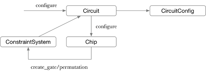
In this sample, the circuit applied for 2 Columns Advice ,1 Column Instance and 1 Column Fixed. Meanwhile, the circuit constructed a multiplication Gate:
vec![s_mul * (lhs * rhs - out)]This multiplication Gate is a constraint expression. Note that the difference from other zero-knowledge proof constraint system is one constraint can use Cells from multiple rows. The call diagram shows below:
- Synthesize Process
After circuit Configure is done, it’s time to call synthesize to integrate a circuit. The call diagram shows as follows:
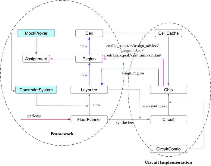
The Chip calls function assign_region to assign Regions for Layouter, and calls functions of constrain_constant/constrain_equal for the Region. Please check the function mul of FieldChip:
impl<F: FieldExt> NumericInstructions<F> for FieldChip<F> {
fn mul(
&self,
mut layouter: impl Layouter<F>,
a: Self::Num,
b: Self::Num,
) -> Result<Self::Num, Error> {
let config = self.config();
let mut out = None;
layouter.assign_region(
|| "mul",
|mut region: Region<'_, F>| {
config.s_mul.enable(&mut region, 0)?; //获取到一个Region后,enable该row对应的乘法selector。
let lhs = region.assign_advice( //对两个advice进行赋值
|| "lhs",
config.advice[0],
0,
|| a.value.ok_or(Error::SynthesisError),
)?;
let rhs = region.assign_advice(
|| "rhs",
config.advice[1],
0,
|| b.value.ok_or(Error::SynthesisError),
)?;
region.constrain_equal(a.cell, lhs)?; //限制两个advice和之前的load的Cell一致
region.constrain_equal(b.cell, rhs)?;
// Now we can assign the multiplication result into the output position.
let value = a.value.and_then(|a| b.value.map(|b| a * b));
let cell = region.assign_advice( //对乘法的输出进行赋值
|| "lhs * rhs",
config.advice[0],
1,
|| value.ok_or(Error::SynthesisError),
)?;
// Finally, we return a variable representing the output,
// to be used in another part of the circuit.
out = Some(Number { cell, value });
Ok(())
},
)?;
Ok(out.unwrap())
}
...
}Summarize:
Start to understand Halo2 with two parts: 1/ circuit construction 2/ proof system. From a developer’s perspective, circuit construction is the programing interface. The key to understand circuit construction is to figure out how to build circuits, and how these circuits are represented within Halo2. Halo2’s Chip circuit is made up with multiple Regions. Within the Halo2 framework, Chip is composed of Regions, and these Regions are organized by Layouters. All information of the circuit is stored in Assignment interface. Halo2 circuit construction can be divided into two parts:1/Configure 2/ Synthesize. Configure is to configure the circuit’s own settings, while Synthesize is to assign a circuit’s variables.
